Pre-flight Testing
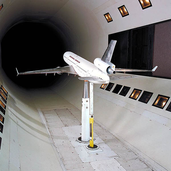
Scale aircraft in a wind tunnel (NASA, Wikimedia Commons)
Scale aircraft in a wind tunnel (NASA, Wikimedia Commons)
How does this align with my curriculum?
Learn about some of the ways Aerospace engineers test new designs.

Image - Text Version
Shown is a black and white photograph of aerospace engineer Wernher von Braun and a Saturn V rocket.
von Braun is in the foreground. He is a middle-aged caucasian man with blond hair. He is wearing a long-sleeved white button-down shirt, grey pants and a dark-coloured tie. He is in a relaxed pose with his left hand in his pant's pocket. He is looking slightly away from the camera. He is standing on a gravel path leading to a Saturn V rocket and a launch tower. The rocket is a long white cylinder that tapers to a point. Black rectangular patches can be seen in several places on the rocket. The tower supports the rocket below and from behind.
Testing Before Flying
As you can imagine, flying is an activity in which mistakes can be deadly. This is why aerospace engineers test every part of a new aircraft or spacecraft. This testing happens long before any person flies them! Early testing can include placing of the craft in a wind tunnel, flying scale models of the aircraft or spacecraft, and testing pieces of the new craft on the ground.
Wind Tunnel Testing
are tools used by aerospace engineers to investigate how air flows around a solid object. Using a wind tunnel, engineers can vary the speed and direction of moving air relative to an object in a controlled way. They can observe how the object affects the airflow.

Image - Text Version
Shown is a colour illustration of a clay car model in a wind tunnel.
The car model is on the floor of a large room. Yellow markings on the floor show where test objects should be located. The car has a sporty design. It is a pale brown colour. It has wheels. Windows and other details are inscribed into the clay. In front and slightly ahead of the car is a large fan that appears to be turning. Streams of smoke are released from a pole slightly in front of the car. The streams flow up and over the car in roughly parallel lines.
Did you know?
The first wind tunnel was designed and built by Francis Wenham and John Browning in England in 1871.
 fan assembly of the wind tunnel at the German Research Institute for Aviation in Berlin, 1935")
Image - Text Version
Shown is a black and white photograph of a giant fan in a wind tunnel in Berlin in 1935.
The fan dominates the image. It has an 8.5 metre diameter and six huge fan blades. Six men in business suits can be seen walking towards and between the fan blades. The fan is not running! Each blade is about twice as tall as a person.

Image - Text Version
Shown is a black and white photograph of a Mercury space capsule in a wind tunnel at NASA's Langley Research Center in 1959.
The wind tunnel is in the background. It is shaped like a horizontally aligned rectangle, but with rounded corners. A large four-bladed fan can be seen at the back of the tunnel in the shadows. At the front of the tunnel, the capsule is held by two metal arms attached perpendicularly to two hydraulic pistons. The capsule is upside down and slightly angled towards the fan. Lights are reflected off the capsule's shiny metal surface. A man atop a tall step ladder is near the left-hand piston arm. He is looking in the direction of the capsule.
There are many different types of wind tunnels designed to simulate different airspeeds. High-speed wind tunnels usually have very small diameters. This is because as air is forced through a smaller opening, its speed increases. This is in action. Large wind tunnels, like those that hold full-scale objects, are usually for speeds. Aside from observing the object in the wind tunnel, instruments can be fitted to the object to measure air pressure at various points on the subject.

Image - Text Version
Shown is a colour photograph of a tennis ball in a wind tunnel. The background is black and the tennis ball is a pale yellow colour. Parallel streams of white mist flow past the tennis ball. Above and below the ball, the streams remain mostly parallel. Directly behind the ball, the mist looks more like a cloud. A light coming from the left side shines on the tennis ball and illuminates the mist.
One of the biggest advantages of wind tunnels is that engineers can observe and photograph exactly what happens to an aircraft or spacecraft as it is being tested. Tests can also be easily repeated in a wind tunnel. This is much harder to do with flight testing. Wind tunnel tests are obviously safer, too, because nobody is in the vehicle being tested!

Image - Text Version
Shown is a computer-generated image of the airflow around the space shuttle as it comes in to land. The space shuttle appears as a greyish shape in the foreground. Below and training behind the shuttle are streaks of blue, greens and yellows.the colours illustrate different levels of turbulence created by the shape.
Flying Models
Wind tunnels and computer simulations have their uses. But the best way to test an aircraft is to actually fly it. This doesn’t always mean using the real full-sized aircraft. Aerospace engineers often use small-scale models to test aircraft and spacecraft designs before the real aircraft is built. This can help to find problems with the design. Flying models also help to the data produced by wind tunnels and computer simulations, which improves their accuracy.

Image - Text Version
Shown is a colour photograph of four engineers and their radio-controlled test models.
The engineers and the models are on a large, flat, dry lakebed. Hills can be seen far off in the distance. Two of the men are standing and two are crouching near the models. They are all wearing button-up short-sleeved shirts and pants. One is wearing a baseball hat and two are wearing sunglasses. In front of the men, lined up on the ground, are the six test models. All have very angular, pointy designs. They are a variety of colours including white, orange, grey and black. Two radio controllers are also sitting on the ground near the test models.
Avro Arrow
Image - Text Version
Shown is a black and white photograph of an artist's drawing of the Avro Arrow from around 1955. The aircraft is in flight above the clouds, climbing from the lower right to the upper left.
The Arrow is a jet that looks like it is made from triangles. The wings are swept back triangles, the tail is triangular as are the nose and even the cockpit windows. The opening for the long rectangular air intake can be seen at the leading edge of one of the wings. Royal Canadian Air Force rondels can be seen on the air intake and on the wings. This aircraft has the designation CF 201.
The Arrow was designed to fly at Mach 2 , or approximately 2 000 km/h or 1 320 MPH at high altitudes. But this was faster than available wind tunnels could accurately simulate. To solve this problem, Avro engineers had to figure out another way to gather high-speed data about the Arrow’s performance, stability, and at supersonic speeds.
They decided to fire Free Flight Test Models of the Arrow into the air using rockets. Each model was 2.7 metres (9’) long, which was 1/8 the size of the real aircraft. Each model was attached to a Nike-Ajax missile booster that produced 490 N (50 000 lbs.) of thrust. The rockets propelled the models to a speed of around Mach 2. Total flight time was about 30 seconds. About 8 seconds of that was supersonic.
Avro engineers tested the models at the missile range at the Canadian Armament Research and Development Establishment (CARDE) in Point Petre near Picton, Ontario. Nine of these models were fired out over Lake Ontario from 1954 to 1957. Two more were shot from the National Advisory Committee for Aeronautics (NACA) test range at Wallops Island, Virginia. Sadly for the Avro engineers, not much data was gathered from these tests.
The rockets and models performed as the engineers expected. But the cameras and that was supposed to track the models did not work well at all. The only useful data gathered was the from the models. What the engineers learned most was the importance of good instruments for recording tests.
Image - Text Version
Shown is a black and white photograph of the official roll out of the Avro Arrow. The photo is taken from a bird's eye view, likely from atop a nearby building. The top of the aircraft takes up most of the picture. It is an angular, bright white plane. Royal Canadian Air Force markings are visible on the wings and side of the fuselage. The aircraft has the designation RL 201. Surrounding the plane, behind a rope line, are throngs of people eager to see the new plane. Off to the left is a platform where dignitaries are standing.
The Free Flight Models, though, are still out there somewhere. Once their flights were over, the models kept going until they fell into the waters of Lake Ontario about 10 kilometres offshore. Recently, several groups have tried to find and recover these models using and underwater cameras. So far, only pieces of one model have been recovered. The Arrow Free Flight Model tests did not provide the data that the engineers had hoped, but they did provide some sunken treasure that is still waiting to be found in Lake Ontario!
Testing Rocket Engines
Rocket engines are only used for a short time during any space mission. But the success and safety of every space mission depends on those engines working properly. A rocket engine needs to burn for exactly as long as needed and provide exactly as much thrust as expected. If it doesn’t, the spacecraft could fail to reach the desired or, even worse, the engine and rocket could explode. As a result, rocket engines are thoroughly tested.
The engineers in Wernher Von Braun’s team at the Marshall Space Flight Center, in Huntsville, Alabama, were some of the thousands of people who worked on the United States’ Apollo Moon program.
These engineers developed the F-1 rocket engine. Five of these engines powered the first stage of the huge 110m (363’) tall Saturn V that would send astronauts to the Moon.
The F-1 was a huge engineering challenge. Each engine needed to produce more than 6.67 x 10⁶ N (1.5 million pounds) of thrust. Not only that, the thrust needed to last for more than 2.5 minutes. When running, each F-1 engine would use 3 tonnes of per second. Since the Saturn V had five of these engines, it burned 15 tonnes per second!

Image - Text Version
Shown is a colour photograph of an F-1 engine on a test stand in California in 1964. The stand is a large metal structure that has an opening at the bottom. In the opening the F-1 engine can be seen. Streaks of orange fire and clouds of hot yellow gases can be seen directly between the engine and the ground. At the top of the structure are two large spherical fuel tanks. At the top of the structure appears to be a large crane.
The testing done by the engineers in Huntsville and elsewhere helped to create a near-perfect engine. Every one of the 65 engines used in Saturn V launches worked flawlessly.
In Conclusion
Long before a new airplane or spacecraft takes to the skies, aerospace engineers have spent thousands of hours testing the design and the parts. These tests help make air and space travel better and safer.
Learn More
What Are Wind Tunnels?
This page from NASA provides a good explanation of wind tunnels and how they are used to design aircraft and spacecraft.
Testing Parachutes for Mars
This article, by Let’s Talk Science, shows how wind tunnels were used to test parachutes designed for space probes.
After decades of failed searches, the 'holy grail' of Avro Arrow artifacts uncovered at the bottom of Lake Ontario (2020)
This National Post article is about the Avro Arrow and how a team from Raise the Arrow found one of the test models.
Raising the Avro Arrow
The Canada Aviation and Space Museum resources about the Avro Arrow and the search for the test models.
Human Spaceflight: The First 50 Years
This article, by Let’s Talk Science, has information about early space missions that used the Saturn V rocket.
References
Boom (Aug 10, 2021). What Is Wind Tunnel Testing?
Chong, B. J. (Feb 7, 2007). Avro Arrow. The Canadian Encyclopedia.
Hall, N. (May 13, 2021). Wind Tunnel Testing. NASA.
Hitt, D. (Apr 5, 2017). What Are Wind Tunnels? NASA Knows!
Young, A. (2008). The Saturn V F-1 Engine: Powering Apollo into History. Chichester, United Kingdom; Praxis Publishing House.